- Table of Contents
Introduction
The VIPA is a relatively new interferometric device. It is based upon the principle of a side entrance etalon. The device is composed of two plane parallel mirrors with one a total reflector and the other a partial reflector. The incident angle and the single sided exit for the device ensure both high spectral dispersion and optical efficiency.
The LightMachinery VIPA calculator is a simple design tool for determining the performance of a VIPA etalon. The tool contains two mathematical models for modelling VIPA transmission. The first calculates VIPA performance using a paraxial solution1,2 and the second, from a more recent paper includes the effects of dispersion3. Reference papers used in the development of this calculator can be found in the Bibliography at the end of this note.
VIPA Principles
The virtually imaged phase array (VIPA) is a high resolution, wavelength dispersion device. Initially finding application in wavelength division multiplexing/demultiplexing2 for telecommunications, VIPA’s high resolution, high dispersion properties have been utilized in optical fibre dispersion4 and pulsed laser chirp compensation5.
A VIPA is composed of two plane parallel mirrors, one a near total reflector and the other a partial reflector, Figure 1. The light source of interest is focused to a waist using a cylindrical lens. The input beam is typically input to the VIPA at one edge at near normal incidence. The near normal angle of incidence ensures that many reflections between the two surfaces occur along the VIPA’s length.
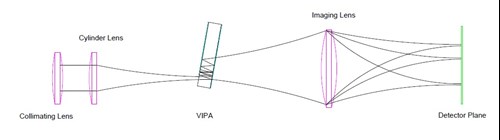
Figure 1, Simple VIPA Layout
Optimum coupling of the input beam to the VIPA without clipping occurs when the waist of the input beam is placed on the surface of the partial reflector. The mode is then of equal size at the input to the VIPA and on its first bounce off the total reflector. A tightly focused waist and a small transition zone from transmission to total reflection on the first surface ensures that the VIPA incident angle is kept small. This increases the number of round trips per unit length of the VIPA and keeps the over device length small.
The optimum VIPA size is determined by the input mode, output surface reflectivity and incident angle. The input beam, such as from an optical fiber is first collimated, determining the VIPA width. A cylindrical lens is then used to form a tight line focus as noted above. With each round trip a small portion of the input light exits the VIPA. VIPA output surfaces are typically greater than 90% reflectors over the wavelength range of interest. The number of round trips is then determined by:
IR / IO = (R x r)N where: IR / IO is the intensity fraction
R is the reflectivity of the high reflector
r is the reflectivity of the partial reflector
N is the number of bounces
By picking a fraction of the input intensity below which beam interference is ignored (typically 1%), the number of round trips can be calculated. Combined with the increasing mode diameter along the length of the VIPA, and its incident angle, the required length of the VIPA can be calculated.
Along the VIPA length, interference between the overlapping mode round trips produces a wavelength dispersing response. Each VIPA round trip appears as a series of displaced beams each having a fixed phase relationship.
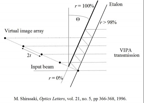
Figure 2, Virtual Image Phase Relationship
The transmission from the VIPA is then brought to a focus with an output lens. The lens resolves the spectral content of the input beam at the lens focal plane in a direction perpendicular to the input beam. The intensity function of the output is given by:
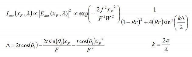
where: W is the collimated input mode diameter
xF is the position along the focal plane x axis
λ is the input wavelength
F is the focal length of the output lens
f is the focal length of the input lens
Δ is the phase difference, when kΔ is a multiple of 2π transmission maxima occur
Using the paraxial approximation, the wavelength dispersion of the VIPA can be rewritten in terms of an angular dispersion originating at the z position of the output focal lens:
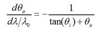
where: θo is the output angle
θi is the incident angle
It is important to note that the dispersion is not a linear function but determined by angular position in the output plane.
Both the older Xiao-Weiner and Hu-Sun models include the increase in bandwidth which occurs when VIPA length limits the number of mirror reflections.
Calculator Features
The VIPA calculator used by LightMachinery adds several helpful features beyond the basic VIPA theory outlined in the previous section:
Index of refraction – the model includes the VIPA index in its calculation allowing it to model both parallel mirrors in air and solid VIPAs.
Transition AR to HR – the calculator also includes the ability to adjust the transition between the AR coated region of the VIPA input and the HR coating. The calculator uses this transition in its calculation of the angle between the VIPA and the incident light. The angle is set to avoid clipping of the input beam mode.
Surface Irregularity – a statistical evaluation of the impact on finesse of surface variations in manufacturing has been included in the calculator.
Calculator Operation
Basic VIPA Design
The key design parameters of the VIPA device are combined in the first group box.
Incident Wavelength – this is the nominal spectral range at which the VIPA operates and is used in the plots of VIPA performance. This value is also used to calculate the wavelength dependence of the Index of Refraction for the predefined materials.
Second Wavelength – an optional second wavelength is available in spectral plots, and can be used to study the wavelength resolving power of the device.
Input Mirror Reflectivity – the calculator assumes a reflectivity of 99.9 % for the total reflector on the input side of the VIPA. The value of the reflectivity can be varied, if required.
Output Mirror Reflectivity - The reflectivity of the output partial reflector can be set by the user. The mirror reflectivities determine the VIPA resolution and impacts the length of the device.
Mirror Separation – this is the thickness of a solid VIPA or the distance between the two mirrors of an air spaced VIPA device. Mirror separation in combination with the input angle determines the FSR of the VIPA.
VIPA Length - the device length is used in the calculation of the number of reflections between the input and output mirrors. Short lengths can impact the finesse and resolution of the device.
VIPA Material - The material is used to calculate the refractive index between the VIPA mirrors. The index of commonly used optical materials can be selected using the dropdown box or by selecting “User Defined” the user can input their own value of the material refractive index to the calculator.
VIPA Model - Two models are available: Xiao-Weiner and Hu-Sun. The Hu-Sun model is based upon interference theory and results in a more exact analytical treatment of device dispersion. The Xiao-Weiner model based upon a paraxial approximation has been included for comparison.
Tolerances
Transition AR to HR – this value is used to show the impact of the transition zone between the anti-reflection coating and the high reflection coating on the input surface. The width of the transition zone increases the minimum input angle required to ensure no clipping of the input beam occurs. This value is used to calculate the minimum angle required for low loss operation of the VIPA. The user can vary the input angle by selecting a large or small transition zone.
Surface Irregularity – this value represents the small scale surface imperfections remaining after polishing the VIPA surfaces. This value is used to determine the impact on finesse of a Gaussian distribution of defect heights. This value represents the sigma value of this distribution.
Input/Output Lenses & Beam
The values of the optics which combined with the “Basic VIPA Design” parameters determine the VIPA optical properties.
Input Cylinder Lens – the focal length of the cylindrical input lens. In combination with the wavelength and the input mode diameter this determines the Input Waist Inside the VIPA.
Output Lens – the focal length of the lens which determines the wavelength dispersion of the VIPA.
Incident Beam Diameter – the beam hitting the input cylindrical lens is roughly collimated. The user can input the diameter of this collimated beam to the calculator. This value in combination with the wavelength and the focal length of the input cylinder lens determines the beam waist at the input to the VIPA.
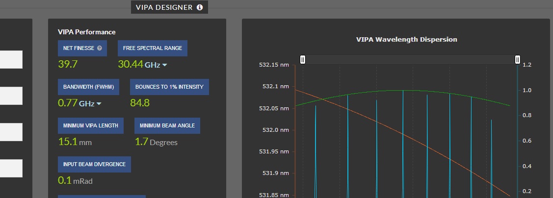
VIPA Performance
The VIPA performance values are combined in the final group box on the top right corner of the calculator. The tabulated values include:
Optical Index - when the VIPA Material is selected, the index of the optical material is used to determine the actual optical thickness of the material. The user can select a range of materials, or air. If User Defined is selected the user can enter a custom index value.
Net Finesse (RMS) – the Net Finesse box contains the contribution of the surface roughness to the reduction in the theoretical maximum finesse of the device. (see box below Net Finesse for the theoretical maximum finesse)
Theoretical Finesse - the calculated Finesse of a perfect etalon with zero surface irregularities.
Free Spectral Range – the spectral range of the VIPA before wavelength overlapping occurs.
Bandwidth (FWHM) – this is the numerically interpolated bandwidth of the VIPA and includes the impact of surface irregularity. The bandwidth can be thought of as the smallest difference in wavelengths that can be distinguished at the incidence wavelength, λ.
Reflections to 0.1% – This is the number of light bounces until the initial intensity drop to 0.1%, based upon the reflectivity of the partially transmitting output mirror.
Length Limited Reflections - This is the number of possible mirror reflections along the length of the VIPA. If the length limited reflections is less than the reflections to 0.1% reflectivity it is likely that length is impacting the resolution of the device.
Minimum VIPA Length – a geometric estimate of the minimum VIPA length required to ensure the finesse is not reduced by an insufficient number of reflection of the VIPA (based upon the number of reflections to 0.1% and the angle of incidence of the input beam).
Incident Beam Angle – the angle in degrees calculated from the mode size and the transition between AR to HR such that no clipping of the mode occurs.
Pixel Bandwidth - the calculator, as part of its analysis options allows the user to select a detector array for recording the VIPA spectral output. This value represents the spectral resolution in pm/pixel resulting from the choice of input/output lenses, and pixel size. Ideally, the Pixel Bandwidth should be at least 3X smaller than the VIPA bandwidth to ensure the VIPA resolution is not pixel limited.
Input Beam Waist – the calculated Gaussian mode diameter at the input to the VIPA. This can be used to estimate the power density at the input to the VIPA.
F/# of Spectrometer - a estimate of the light gathering capability of the input optics.
Spectrometer Resolving Power - this is a measure of the VIPA's ability to resolve closely-spaced wavelengths. It is defined here as the free spectral range divided by the bandwidth.
Finesse Calculations
The calculator uses a distribution of VIPA thicknesses to model thickness variations of surface roughness. The distribution of thicknesses results in small shifts in the angular dispersion of a given wavelength, hence deceasing the finesse of the device.
Program Work Flow
The calculator has been arranged so that there is a natural flow from left to right during analysis. The user first enters the basic VIPA parameters. The input and output lenses which meet the performance requirements can then be selected to determine the input tuning angle and mode diameter. The manufacturing tolerances and their impact on finesse can now be explored. The characteristic VIPA device performance can now be read in the group box in the center top of the screen. By selecting one of the radio buttons along the center bottom, the plot of interest can be displayed.
Chart Controls
In the upper right of the chart tool is a menu for controlling the chart display. More details on using this menu can be found at:
https://plotly.com/chart-studio-help/getting-to-know-the-plotly-modebar/
References
1 - S. Xiao, A.M.Weiner, and C. Lin, “A dispersion law for virtually imaged phased-array spectral dispersers based on paraxial wave theory,” IEEE J. Quantum Electron. 40, 420–426 (2004).
2 - S. Xiao, A.M.Weiner, and C. Lin, “An Eight-Channel Hyperfine Wavelength Demultiplexer Using a Virtually Imaged Phased-Array (VIPA),” IEEE PHOTONICS TECHNOLOGY LETTERS, vol. 17, no. 2, Feb. 2005.
3 - Xinrong Hu, Qiang Sun, Jing Li, Chun Li, Ying Liu, and Jianzhong Zhang, "Spectral dispersion modeling of virtually imaged phased array by using angular spectrum of plane waves," Opt. Express 23, 1-12 (2015)
4 - M. Shirasaki, “Large angular dispersion by a virtually imaged phased array and its application to a wavelength demultiplexer,” Opt. Lett. 21(5), 366–368 (1996).
5 - M. Shirasaki, “Chromatic-dispersion compensator using virtually imaged phased array,” IEEE Photon. Technol. Lett., vol. 9, no. 12, pp. 1598–1600, Dec. 1997.


