- Table of Contents
Grating based spectrometers and monochromators are industry staples for spectral analysis. The LightMachinery Grating calculator is a simple design tool for determining the approximate performance of a grating, taking into account basic grating parameters like blaze angle, ruling period, and length. The tool calculates grating performance using a scalar theory of diffraction1. Reference papers used in the development of this calculator can be found in the Bibliography at the end of this note.
An optical grating acts as a wavelength dispersive element by diffracting or refracting light from a periodic structure. This structure can be regular slits or index variations in transmission or ruled lines in a mirror surface in reflection. As with a pair of slits, the diffraction of light from a grating occurs as a result of constructive and destructive interference of light.
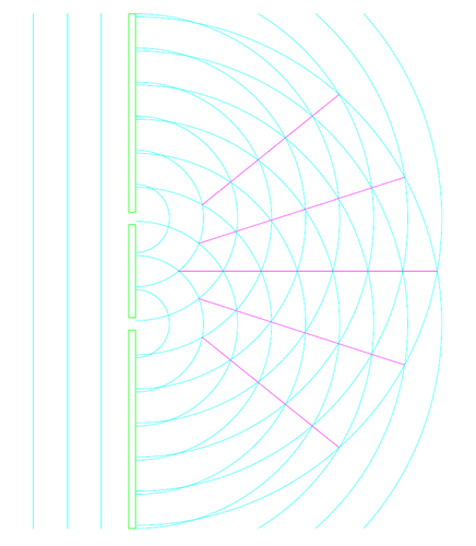
Figure 1, Diffraction Orders from a Double Slit
The equation for double slit diffraction is:
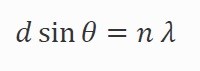
Where Ɵ is the diffracted angle, d is the slit spacing, n is the order and λ is the wavelength of the diffracted light. A specific wavelength of light is diffracted into multiple angles which correspond to constructive interference.
The model chosen for this calculator estimates the performance of a reflection grating with regular ruled lines. As such the dispersion equation must include both incident and diffracted angles. The angle of dispersion for a given wavelength of incident light is determined by the period of the rulings according to:
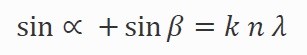
Where ∝ is the angle between the incident light and a perpendicular to the plane of the grating, β is the angle between the diffracted light and a perpendicular to the plane of the grating, k is the period (mm/line), n is the diffraction order and λ is the wavelength.
The efficiency that the grating diverts light into a particular order can be modified by varying the angle of the ruling surface to the grating perpendicular. This technique allows the light in one order to be maximize while suppressing the residual power in other orders.
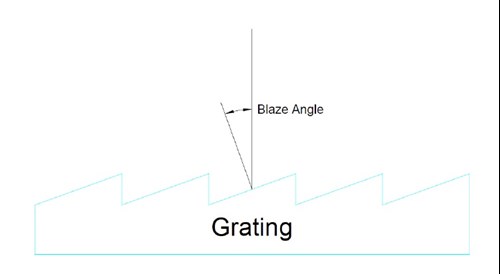
Figure 2, Grating Blaze Angle
The LightMachinery grating model is based upon a Czerny-Taylor monochromator or spectrometer with input and output legs of equal length, Figure 3.
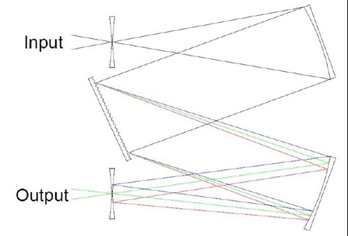
Figure 3, Simple Monochromator
Light enters through an input slit and expands through diffraction to fill the grating. The number of illuminated grating rulings determines the resolving power of the grating.
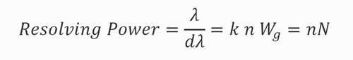
Where λ is the wavelength of the central peak, dλ is the width to the first minima, k is the ruling period, n is the order, Wg is the illuminated width of the grating and N is the number of illuminated rulings. This is the maximum resolution of the device, in practical terms the entrance and exit slit size and arm length, aberrations in grating and optics manufacture and étendue (light transmission through the spectrometer) will limit the resolving power of the instrument.
The calculator attempts to estimate the resolution of the grating spectrometer by calculating the diffraction of light from the entrance slide through the input arm to determine the illuminated portion of the grating. It also calculates the resolution set by the pixel size on the output arm of the spectrometer. A message is displayed indicating which design element is limiting the grating resolution.
Once the grating parameters including blaze angle are selected, the spectrometer physical properties need to be inputted. These properties are needed to estimate the resolution of the device. The calculator then models the average spectral intensity response of the grating using a scalar diffraction theory1. Expected spectrometer performance can then be plotted, including dispersion, wavelength calibration, and line width at the grating output.
The calculator provides parameters to customize the grating, spectrometer, and the detector array used. The incident angle of the light from the input slit to the grating perpendicular can be adjusted. Incident light angles from 0 to 90 degrees can be inputted although practically an instrument should operate near the blaze angle for best efficiency. Operating at the blaze angle will give the highest efficiency but this means that the input and output legs of the instrument overlap at the blaze wavelength. In some devices, this may not be practical but designs with very shallow angles between input and output beams can be accommodated with long working arms.
The calculator also allows the user to place a custom linear array at the output focal plane. The array can be shifted with respect to the blaze peak by adjusting the detector centering. The detector can be shifted by +/- 50% of its width with respect to the peak wavelength.
The calculator has been arranged so that there is a natural flow from left to right during analysis. The user first enters the basic grating parameters. The input and output slits and the focal length of the mirrors are then selected. The characteristic spectrometer performance can now be read in the group box in the center top of the screen. By selecting one of the radio buttons along the center bottom, the plot of interest can be displayed.
1 – R. Casini and P. G. Nelson, “On the Intensity Distribution Function of Blazed Reflective Diffraction Gratings”, JOSA A, 31, 2179-2184 (2014)
2 – J. M. Lerner, “Imaging Spectrometer Fundamentals for Researchers in Bioscience”, Cytometry Part A 69A:712-734 (2006)


