- Table of Contents
Introduction
A common application of Fabry-Perot etalons is interferometry where their high finesse and étendu allow them to resolve small optical path differences and wavelength changes in weak signals. Their use in spectroscopic measurements is less common in part because spectral content and line shape must be deconvolved from their circular fringe patterns.
Fizeau wedge based interferometers offer the advantage of equally spaced, and parallel fringes with finesse and étendu comparable to that of an etalon. They can be directly coupled to a detector array without intermediate optics resulting in a compact, robust instrument.
LightMachinery primarily manufactures air spaced, Fizeau wedges. Air spaced Fizeau wedge and Etalon designs are by design more optically stable over temperature than their solid counterparts.
Fizeau Principles
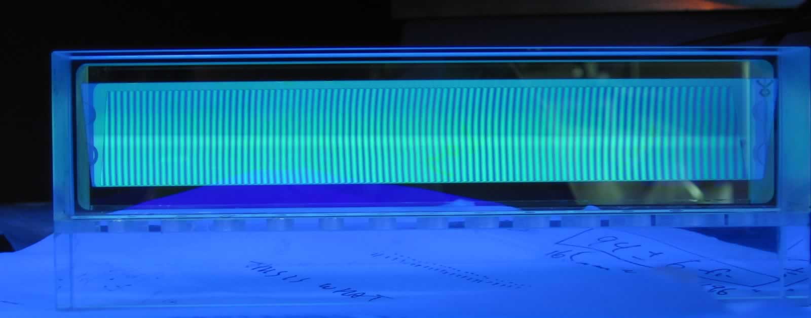
Fizeau fringes form when monochromatic, collimated light is incident upon two planar surfaces forming a slight wedge. Interference occurs between transmitted and reflected wave fronts, fringes occur due to the changing optic path length along the Fizeau width, Figure 1.
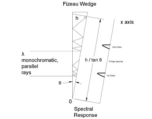
When the angle θ is small the path difference Δl can be described by:
Δl = 2 L sin (θ) ≈ 2 L θ Eq. 1
where L is the distance along the wedge from the origin 0
The phase difference in air is then given by:
Δφ = ω / c Δl ≈ 2 π f / c (2 L θ) or 4 π L θ / λ Eq. 2
The intensity along the wedge in the x-axis at position L is given by the sum of the intensities of the two surface reflections:
Itotal (Δφ) = I1 + I2 + 2 √ (I1 I2)cos (Δφ) Eq. 3
Maxima occur when cos (Δφ) = 1 or Δφ = 2 π n where n is the fringe order.
The position of the Fizeau fringes therefore occur at:
Δφ = 2 π n = 4 π L θ / λ
L = [ n / (2 θ) ] λ Eq. 4
One of the interesting properties of the Fizeau is now apparent; it is possible to make an absolute wavelength measurement by knowing the order and measuring the fringe distance along the wedge from the origin. As noted in Figure 1, the distance from the origin can also be obtained by knowing the wedge angle and the thickness of the Fizeau Wedge at the fringe position.
A second important property can also be derived from this equation, that is the Fizeau’s ability to resolve two wavelengths increases with each successive order.
(L1 – L2) = [ n / (2 θ) ] (λ1 – λ2) = n [ Δλ / (2 θ) ] Eq. 5
One final important point, when Δλ = (λ1 – λ2) of two incident wavelengths exceeds the free spectral range of the Fizeau Wedge, different orders of the two wavelengths will overlap.
Calculator Features
The LightMachinery Fizeau Designer calculates Fizeau Wedge performance based upon design input details. The calculator assumes that the wedge fringe pattern is examined by a detector array on the exit of the device.
By entering design parameters such as mirror reflectivity, wedge angle and wedge edge thickness or separation, the calculator can determine performance and plot the spectral response of two different wavelengths along the detector array.
The spectral plot can be scaled in distance (mm) or in pixel count. Other calculator options include plotting an Airy fringe response (faster) or full Fizeau fringe response (accurate) of the device. The spectral response peak can be examined in greater details by centering the transmission peak on the plot.
Plot details can be downloaded by selecting the 'Download CSV' option in the drop down under the Share button.
Calculator Setup
The calculator is arranged so that the work flow is from left to right. Fizeau design parameters are entered into the text boxes arranged vertically along the left hand side. The calculator is updated once all parameters have been entered the UPDATE button has be pressed.
The calculated Fizeau Wedge performance values are displayed in the center fields and a spectral plot appears on the right. The units for free spectral range and bandwidth can be varied from frequency, to wavelength and to wavenumbers.
Plot analysis options appear below the performance values and can be used to change how the data is displayed.
Fizeau Design
The physical dimensions of the wedge are given by:
- the angle between the planar mirrors (Wedge Angle),
- the separation of the mirrors at their closest location (Wedge Edge Thickness)
- the length along the wedge output determined by the multiplication of the number of elements in a detector array (Number of Pixels) and their size (Size of Pixels).
The reflectivity of the planar mirrors can be varied, determining the Fizeau Finesse or bandwidth for a given fringe order. The wedge edge thickness or the Fizeau wedge length can be increased to increase the fringe order and the resolution of the interferometer.
Notes
As the separation between the mirrors or the reflectivity increases, the rays between the mirrors begin to walk off the input beam axis. This will introduce distortion to the fringe pattern and reduce the finesse and contrast. Introducing an axis tilt between the incident light and the Fizeau Normal will also result in distortion of the fringe pattern. The mathematical model used in the LightMachinery Fizeau calculator takes all of this into account and will accurately predict the output fringe pattern.
References
1 – M. Born, and E. Wolf, Principles of Optics, 7th (expanded) edition, Cambridge, UK, Cambridge University Press, (2002), pages 323 - 334
2 – O. Novak, I. S. Falconer, R. Sangines, M. Lattemann, R .N. Tarrant, D. R. McKenzie, and M. M. M. Bilek, “Fizeau Interferometer system for fast high resolution studies of spectral line shapes,” Review of Scientific Instruments, 82, 023105 (2011)
3 – D. D. Burgess and T. A. Hall, “Measurement of Transient Stark and Zeeman Shifts Using a Fizeau Interferometer,” Journal de Physique, Colloque C 2, supplement au no 304, Tome 28, (mars-avril 1967) p C 2-221
4 – John R. Rogers, “Fringe Shifts in Multiple-Beam Fizeau Interferometry,” J. Opt. Soc. Am./Vol. 72, No. 5 (May 1982)


