Introduction
Etalons are often used to control the spectra of light. The reflectivity of the surfaces controls the finesse (width of transmission peaks), and contrast (difference between minimum and maximum transmitted intensity). But for some applications, once a finesse is chosen, the resultant contrast may not be high enough. So how can this be improved? By sticking two etalons together as it turns out. A dualon effectively has three reflective surfaces: the two outer ones, and a hidden inner one. By carefully choosing the reflectivity of these three surfaces, as well as ensuring that both halves of the dualon are exactly the same thickness, the transmission spectrum will have a much higher contrast than a standard etalon for a given finesse.
Design Details
The reflectivity of the inner surface (R2), is generally much larger than that for the outer surfaces (R1). For example, to get a finesse of 15, R1 should be around 74%, and R2 should be around 98%. If R2 is too low, then the transmission peaks will become a double peaks, each with a peak transmission of 100%, but with a dip between them. As R2 increases, the dip between the peaks gets smaller, and disappears when R2 is the ideal value. When R2 is greater than the ideal value, the peak transmission drops below 100%, but maintains a single peak.
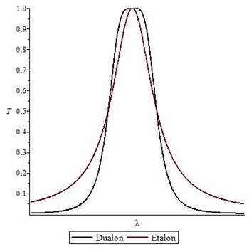
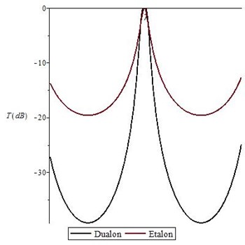
When R2 is the ideal value, the peak shape is much flatter than a standard etalon. The standard etalon has a peak shape of the form 1/(1+x2), where x is the normalized wavelength. For a dualon, the shape is 1/(1+x4), which gives both a flatter top, and higher contrast (reduced transmission away from the peak). These are shown below, as a linear plot near the peak center, and a log plot to show the off-peak transmission.
It is important that both sections of the dualon are exactly the same thickness, otherwise the peak transmission will drop significantly, and the finesse will be reduced. For example, for a dualon designed for a finesse of 15 at 532nm, the peak transmission will drop from 100% to 71% if one of the sections is 5 nm thicker than the other. This is the 'Thickness mismatch' field. Similarly the thickness nonuniformity (quantified by the RMS), will hurt the transmission and finesse.


